Joska. 24 acres for sale
Kes 2.5m per acre
See map below
a4architect posts
Lenyamu/Tinga Land on Sale. 1/4 ac
Kes 350,000
Beacon Coordinates:
1.54707S 36.55752E
1.54839S 36.56016E
1.54675S 36.55926E
1.54873S 36.55846E
Length of the path to shamba from main Magadi Rd. = Approx. 700m
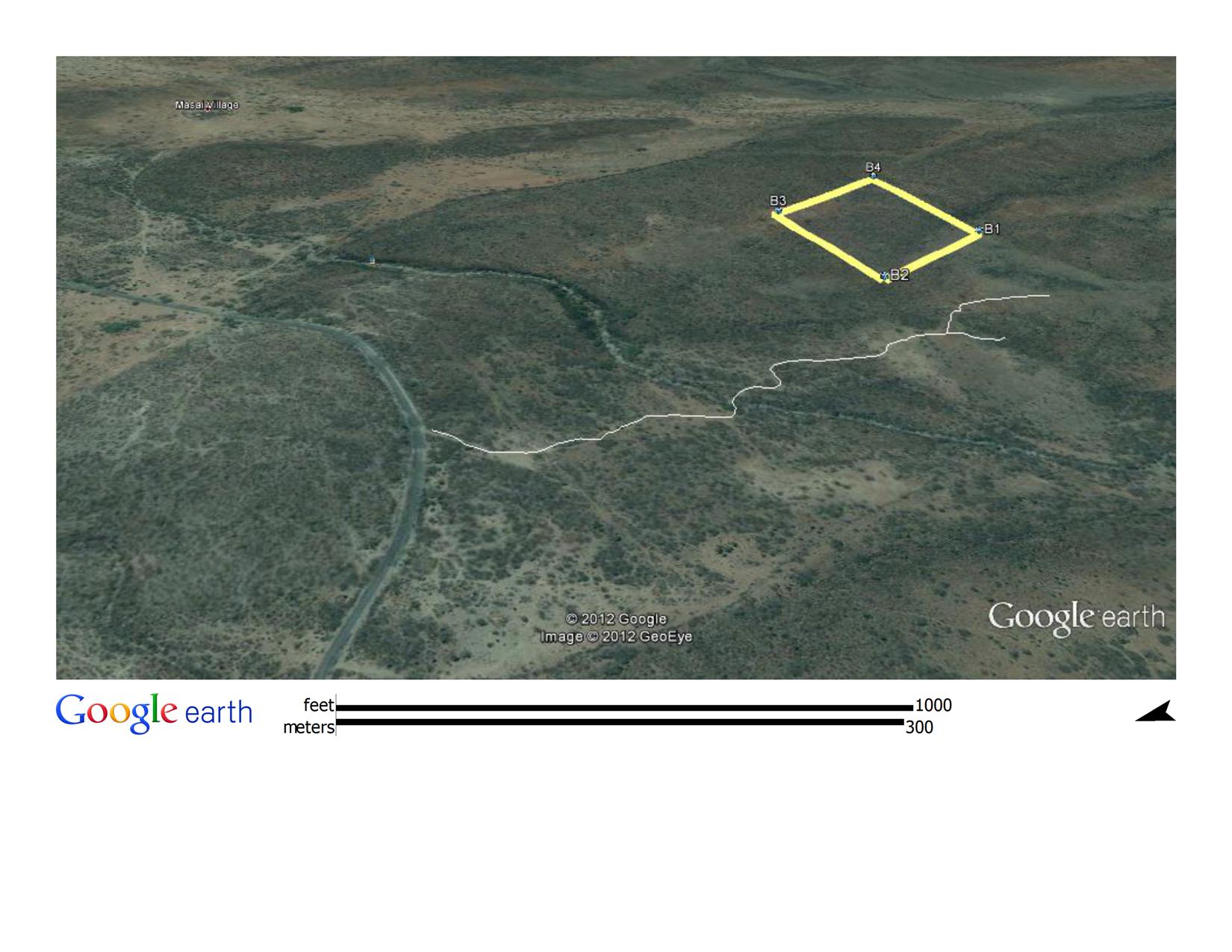
Distance from Kiserian Town = Approx. 28Km
See map here
https://goo.gl/maps/DFAHXphqfC62
Kelvin Papai Looradiak Titles (1) Kelvin Papai Looradiak Titles 

Window blinds come in various materials such as fabric, aluminium and wooden.
Fabric

Fabric blinds can either roll upwards or sideways.
These cost kes 2,000 per m2 inclusive of labour.
Aluminium Blinds.

These roll upwards as in the picture above.
They cost kes 3000 per m2.
Wooden blinds.
These cost kes 12,000 per m2.
They typically roll upwards.
All these are available for delivery within Kenya.
Contact info@a4architect.com
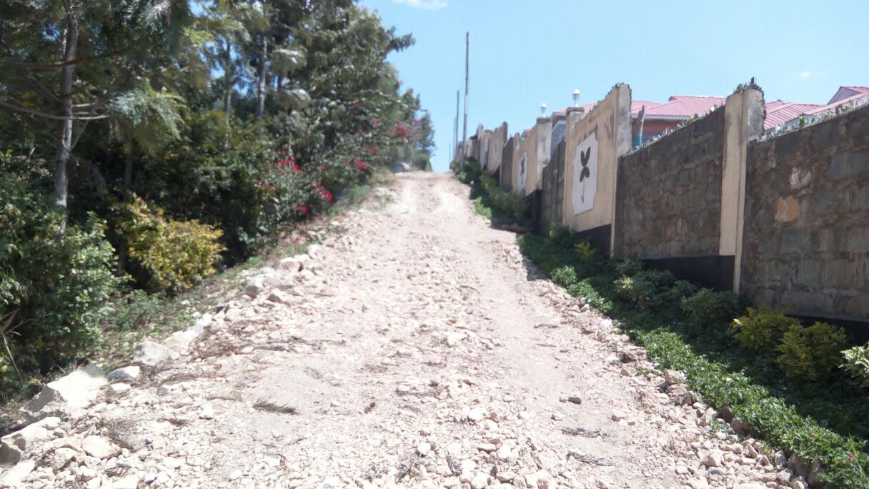
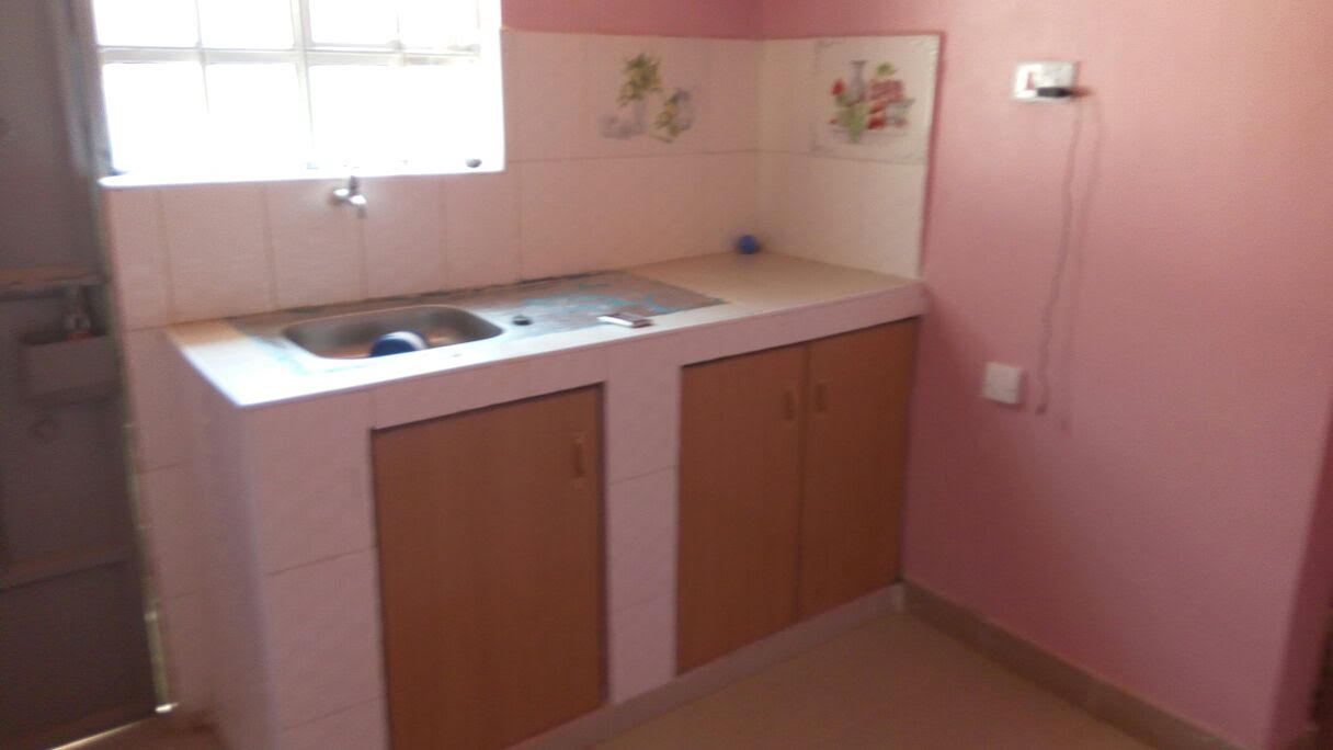
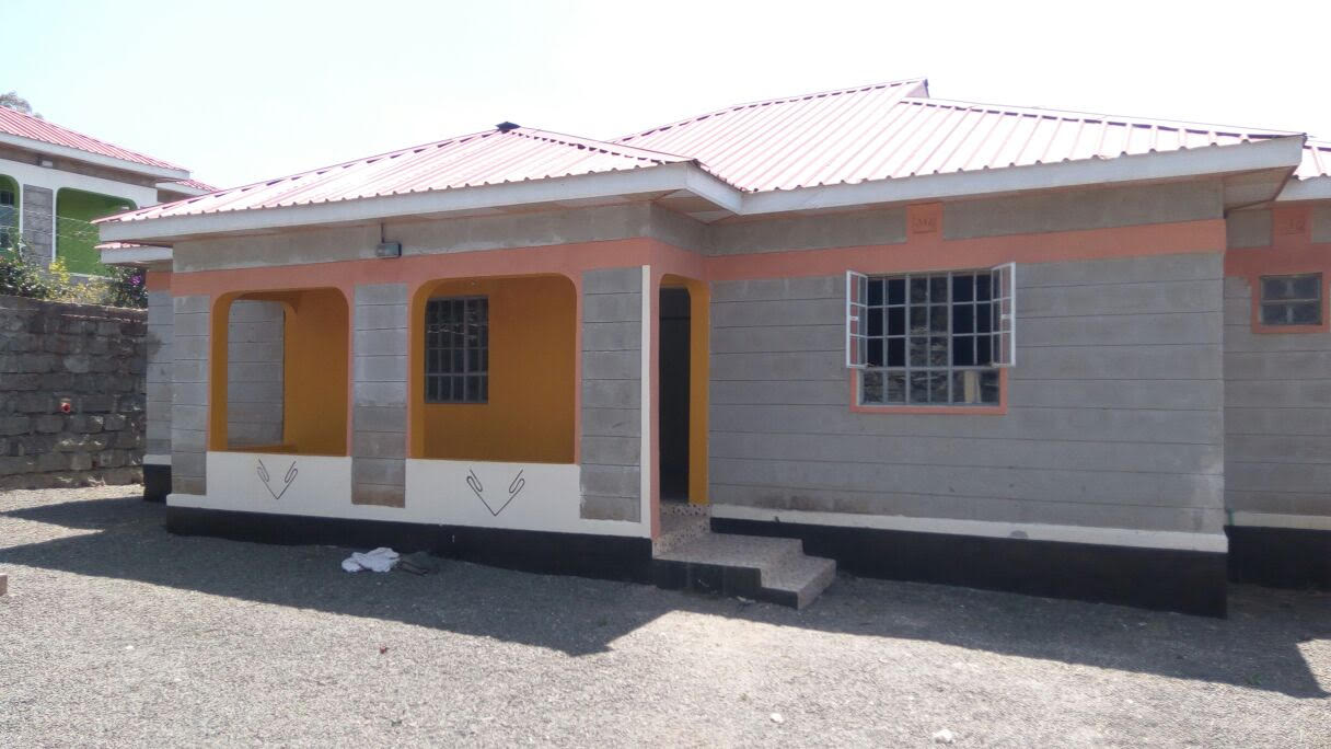
3 Bedroomed House for Sale, Matasia. Kes 5.4m
Email info@a4architect.com.
Call 0721410684
In Kenya, Prefabricated Structural Insulated Panels are slowly gaining popularity within the construction industry.
These panels are mainly used as walls, floor and roof slabs.
The main components of these panels are styrofoam sandwiched in between wire mesh which is then plastered on both sides.
The cement-sand plaster is sprayed on to the panel using a spray gun.
Internationally, this is the way most countries are going in constructing of walls and slabs since the cost is lower.
For Kenya, cost of importation of the styrofoam and wire mesh pushes the panels to roughly same cost as using machine cut stones.
This means as long as machine cut stones remain at the current prices of between kes 50 to kes 60 per piece, this prefab method will be at equal cost with stone walling.
In the long run, as time goes by, the cost of stone will rise due to environmental degradation of quarry mine areas around Juja and depletion of suitable lands to mine stone . At this point, stone walling will be more expensive, paving way for more use of prefabricated wall panels in Kenya.
Structural-wise, these prefabricated panels are not designed to carry vertical load of storeyed construction. Use of Reinforced concrete beams, columns and slabs will still be utilised for load-bearing.
Architect Francis Gichuhi Kamau.
info@a4architect.com
Kileleshwa, Apartment for Sale. KES 18.5m
Durnham Road, Kileleshwa.
1700 sq foot plinth area.
Email info@a4architect.com
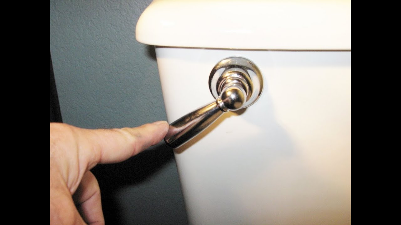
Push button toilets have several advantages over handle flush.
Process of setting out a Building.
1.Students will first identify the site plan which shows the building footprint. Before the work begins, the students need to be able to identify that the architectural plans are stamped by the County Government for approval. This is because if the drawings are not approved, it’s the masons working on the site who are usually picked up and locked in police cells for working on a building that has not been approved as in the case of Kenyan building bye laws.
2.After this identification, the students can then read out the building footprint in relation to the plot boundaries.
In the drawing above, the left side of the building is at exactly the edge of the plot boundary. The top and bottom part are offset from the land plot boundary.
The markings using nylon strings will mark out the foot print as shown in the picture above.
5.Using white lime powder, the building footprint is marked and is now ready for excavation.
For small sized buildings, manual labour is used to excavate.
For larger buildings, use of excavator machinery is more appropriate.
Once the top soil is excavated until stable ground or rock, a more detailed setting out of the internal wall partitions of the buildings can commence.
Once the top soil is excavated until stable ground or rock, a wooden formwork , made out of pine timber, is erected at the edges of the excavation. This forms the support of the nylon strings that are used to measure out the more detailed setting out for the interior walls.
Procedure for setting out.
1.Erection of Sawn timber formwork for foundation.
Once the soil is excavated till stable ground or rock, a 2inch by 2 inch cypress or pine timber post of around 3 feet is driven into the ground on one end of the corner of foundation at ground level.
2.Other pieces are driven into the ground in a spacing of approximately 4 feet apart until the extreme end of the foundation.
This 4inch by 1inch timber plank is what will be later used to support nylon strings that will be dimensioned as per the architectural drawing internal wall.
Francis Gichuhi kamau
Tools used in Pointing and jointing.
1.Trowel.
See the picture below. The man is holding a trowel with his right hand.
This tool is used to scoop put cement mortar and smear it on the masonry stone joints.
The mason below is holding the key jointing tool with the left hand.
This tool is used to embed the key joint in between masonry blocks when the mortar is still wet and soft.
This string is used to enable a mason emboss and imprint the vertical and horizontal lines for working with the key jointing tool.
This tool is used to enable the mason establish perfect horizontal line on the nylon string for a smart key jointing exercise.
Preparing a surface for pointing in masonry walls.
Preparing s surface for jointing of masonry blocks.
Architect Francis Gichuhi Kamau
Making simple working drawings.
Steps.
For complex drawings, Computer Aided Design software on computers is what is needed to fulfill the task.
For simple drawings, the above tools will b effective.
Production of simple Isometric Drawings.
Procedure of making above sketch.
The final outcome is an isometric cube as shown above.
Interpreting a working drawing.
The dimension line is marked by a thin line with the dimension writeen right above it. 4.Read the dimension and note it down then transfer it on the ground.
5.Notice the crossed out mark on the dimension line. This marks the end of the individual measured distance.
Architect Francis Gichuhi Kamau