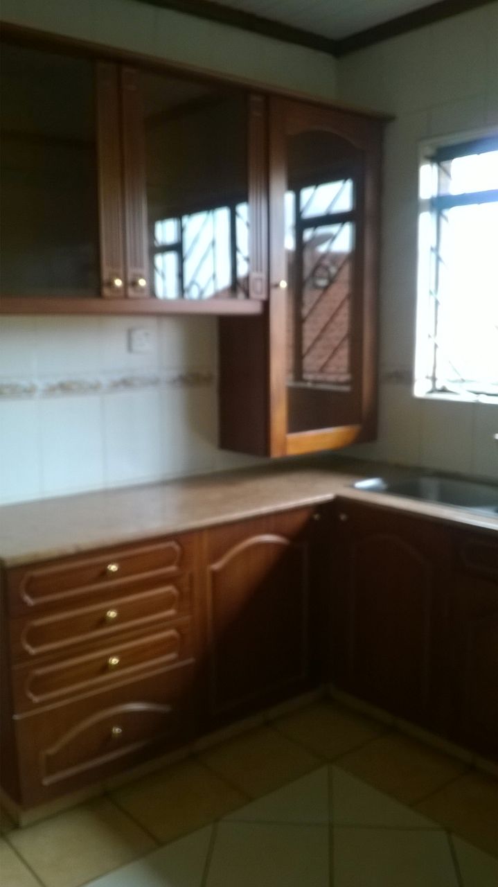
Kileleshwa, Apartment for Sale. KES 18.5m
Durnham Road, Kileleshwa.
1700 sq foot plinth area.
Email info@a4architect.com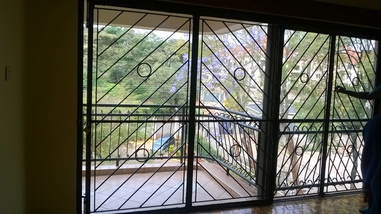
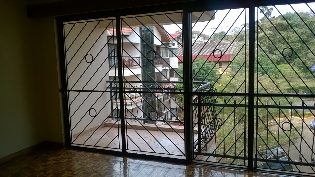
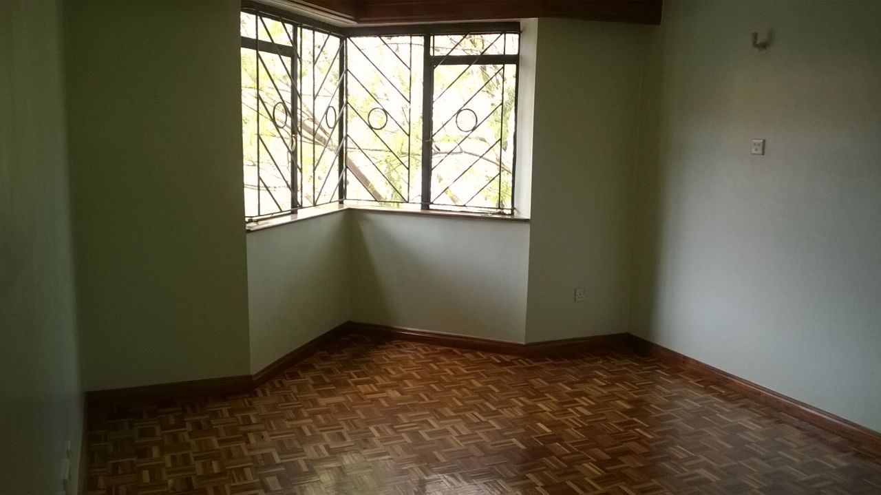
Kileleshwa, Apartment for Sale. KES 18.5m
Durnham Road, Kileleshwa.
1700 sq foot plinth area.
Email info@a4architect.com
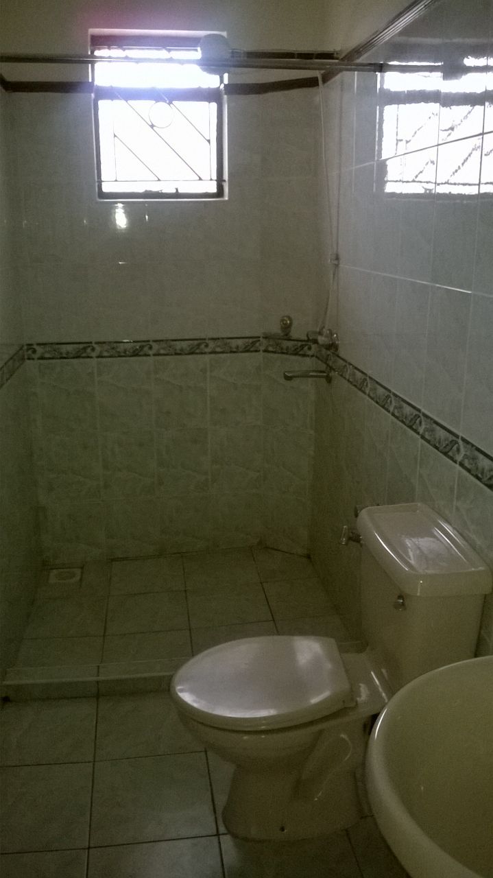
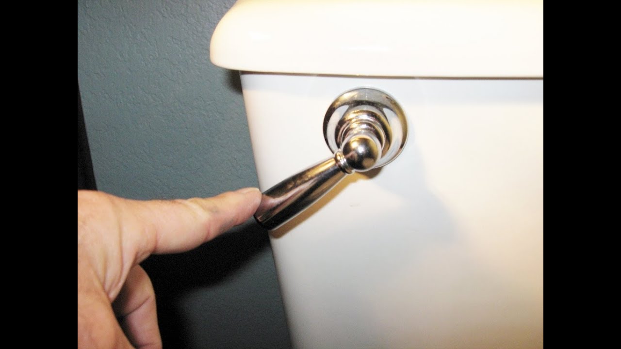
Push button toilets have several advantages over handle flush.
Process of setting out a Building.
1.Students will first identify the site plan which shows the building footprint. Before the work begins, the students need to be able to identify that the architectural plans are stamped by the County Government for approval. This is because if the drawings are not approved, it’s the masons working on the site who are usually picked up and locked in police cells for working on a building that has not been approved as in the case of Kenyan building bye laws.
2.After this identification, the students can then read out the building footprint in relation to the plot boundaries.
In the drawing above, the left side of the building is at exactly the edge of the plot boundary. The top and bottom part are offset from the land plot boundary.
The markings using nylon strings will mark out the foot print as shown in the picture above.
5.Using white lime powder, the building footprint is marked and is now ready for excavation.
For small sized buildings, manual labour is used to excavate.
For larger buildings, use of excavator machinery is more appropriate.
Once the top soil is excavated until stable ground or rock, a more detailed setting out of the internal wall partitions of the buildings can commence.
Once the top soil is excavated until stable ground or rock, a wooden formwork , made out of pine timber, is erected at the edges of the excavation. This forms the support of the nylon strings that are used to measure out the more detailed setting out for the interior walls.
Procedure for setting out.
1.Erection of Sawn timber formwork for foundation.
Once the soil is excavated till stable ground or rock, a 2inch by 2 inch cypress or pine timber post of around 3 feet is driven into the ground on one end of the corner of foundation at ground level.
2.Other pieces are driven into the ground in a spacing of approximately 4 feet apart until the extreme end of the foundation.
This 4inch by 1inch timber plank is what will be later used to support nylon strings that will be dimensioned as per the architectural drawing internal wall.
Francis Gichuhi kamau
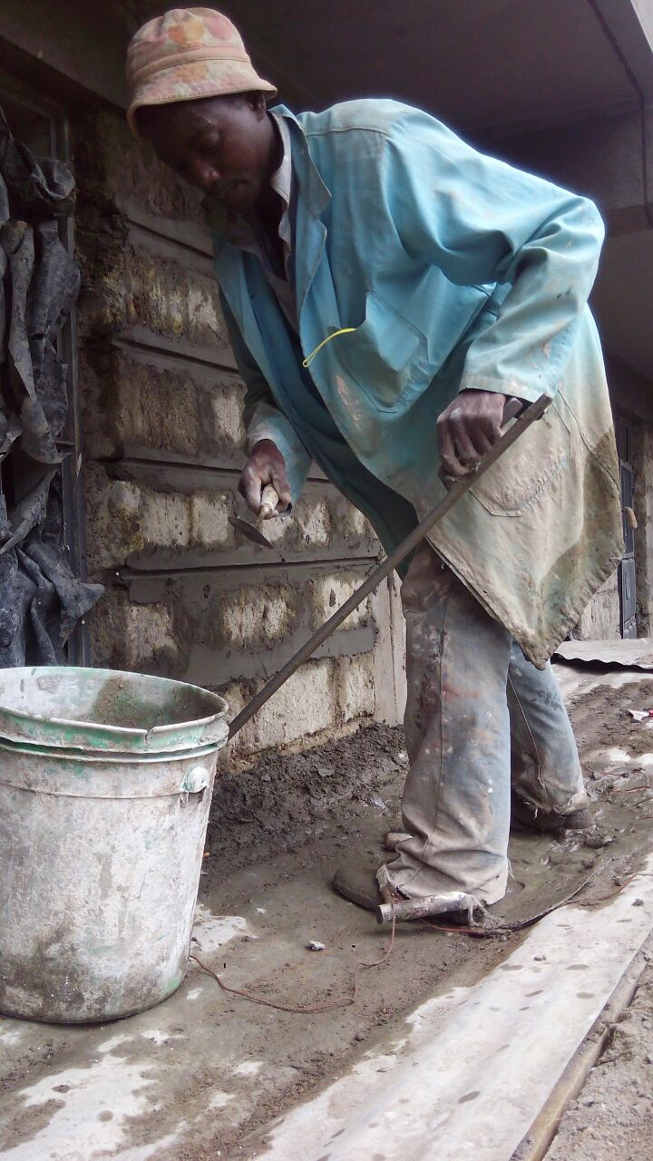
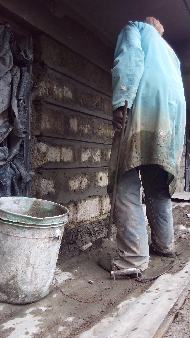
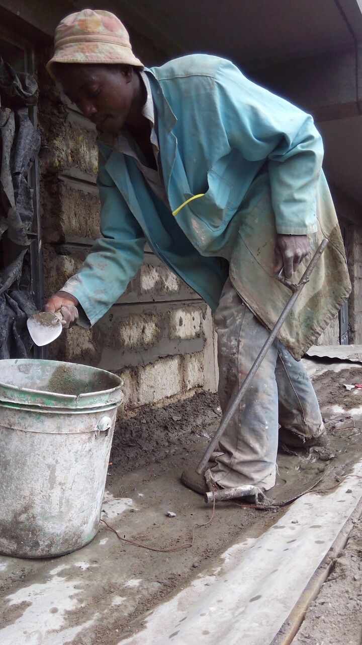
Tools used in Pointing and jointing.
1.Trowel.
See the picture below. The man is holding a trowel with his right hand.
This tool is used to scoop put cement mortar and smear it on the masonry stone joints.
The mason below is holding the key jointing tool with the left hand.
This tool is used to embed the key joint in between masonry blocks when the mortar is still wet and soft.
This string is used to enable a mason emboss and imprint the vertical and horizontal lines for working with the key jointing tool.
This tool is used to enable the mason establish perfect horizontal line on the nylon string for a smart key jointing exercise.
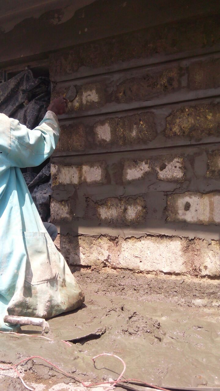
Preparing a surface for pointing in masonry walls.
Preparing s surface for jointing of masonry blocks.
Architect Francis Gichuhi Kamau
Making simple working drawings.
Steps.
For complex drawings, Computer Aided Design software on computers is what is needed to fulfill the task.
For simple drawings, the above tools will b effective.
Production of simple Isometric Drawings.
Procedure of making above sketch.
The final outcome is an isometric cube as shown above.
Interpreting a working drawing.
The dimension line is marked by a thin line with the dimension writeen right above it. 4.Read the dimension and note it down then transfer it on the ground.
5.Notice the crossed out mark on the dimension line. This marks the end of the individual measured distance.
Architect Francis Gichuhi Kamau
Setting out a Building.
Procedures.
1.Once the foundation is excavated, the formwork supporting the sides of foundation is marked as per the dimensions shown in the architectural foundation floor plan.
2.Nails are nailed on the formwork, measured out exactly as shown in the drawing.
The nails on the formwork should be in the same exact dimensions as in the drawings. The wall thickness dimensions should also be captured. This is a very critical dimensioning since the rest of the walls after the ground floor slab is done will be dimensioned the same way. Wall structural loading should be very accurate , where the top floor wallings sit exactly on top of the foundation wallings as marked in the seting out.
Procedure for transferring measurements.
1.Using the architectural drawing, starting from one end of the edge, note the wall thickness and mark it on the wooden support formwork erected at the edge of the foundation.
3.Continue noting the dimensions from the drawings and marking them out progressively from one end towards the farthest end.
5.Repeat this procedure for all the sides and countercheck again to ensure all dimensions are matching as in the drawings.
6.Using the structural engineer’s drawings, use same procedure to set out for column foundation bases.
See the structural engineering drawing above.
Care should be taken to ensure that the strings attached to the wooden formwork are protruding at 90 degrees angle from the timber formwork towards the opposite end.
3 4 5 method of triangulation.
Check above images to see a demonstration of the 3 4 5 method used to recheck if the corners are at right angles together.
Diagonals method for checking right angles.
Procedure.
On the foundation corners, the diagonal ends are measured to ensure that they are of the same size, meaning the foundation is rectangular or square, not hexagonal.
Also, on the edge of the foundation, use of the 3 4 5 method can be done to quickly confirm that the corners are at 90 degrees.
Marking the wall trenches.
Using lime powder, mark the foundation walling trenches then start excavation as per structural engineer’s specifications.
Screeding should then follow suit in readiness for foundation walling and beams.
Architect Francis Gichuhi Kamau.
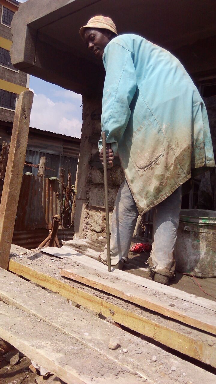
Importance of always wear protective gear and use protective equipment through out the site.
Setting out foundations are amongst the 1st tasks to be carried out in a building construction works. This marks a good start for masons to begin getting accustomed to any new protective gear.
Types of protective gear.
The reflective yellow or orange vests increase visibility, hence enabling more safety.
The gloves prevent masons from being burnt by cement mortar since its very reactive to bare skin.
The boots prevent injury from nails and other tripping objects.
The overalls prevent dirt and other loose clothing from getting entangled by machine moving parts.
Helmets prevent injury from flying objects from the upper levels.
County Government Health department bye laws.
The county government through its health department outlaws any worker/mason from working at a site without proper protective clothing.
Any worker found without this gear by the county inspection team is liable to be arrested and fined in a court of law.
Demonstration of actual setting out.
Procedure.
Architect Francis Gichuhi Kamau
Tools and Equipment used in Setting out a Building.
1.Theodolites.
For large complex buildings, theodolites, survey equipment’s, are used to mark out building external wall extents.
For small scale types of construction, use of long type builder’s square , steel measuring tape are sufficient to demarcate the building external wall extents and internal wall partitioning.
For shorter distances, the steel tape is most appropriate, eg distances between two rooms, thickness of wall while setting out etc.
For larger distances, eg perimeter wall measurement, hexagonal check, the flexible type is most appropriate.
3.Spirit Level
Spirit level is used to ensure that the nylon strings used in setting out are horizontal.
4.Nylon String
Nylon strings are used to demarcate the wall thickness and building extent.
5.Lime Powder
White lime powder is used to mark the foundation walling and column footing positions for further excavation till rock or stable ground.
White lime used to measure out the extents of the building footprint in readiness for excavation.
Notice the wooden formwork that will be used to support the nylon strings to enable setting out.
Notice the effectiveness of white lime powder in effectively marking out foundation dimensions for setting out buildings.
Architect Francis Gichuhi Kamau
How to commence pointing of masonry walls from start to finish.
1.The beginning involves use of masons hammer and chisel to shape out the stone joints to an even line.
2.Water is poured on the stones to enable smooth binding between existing stone and new mortar.
For cobble stone pointing, use of shorter pointing tools is needed.
For zero jointed masonry walls, a very thin pointing tool is used to achieve this.
The end result for zero jointed style is a wall that looks smooth and jointless.
How to identify the difference between architectural and structural engineering drawings.
Structural drawing sample
Architectural drawing sample
Visual identification.
Structural engineering drawings are easily identified from their mostly line work drawings. Architectural drawings have other features such as room furniture, bathroom and kitchen fixtures in them.
Technical identification.
Structural engineering drawings also have letterings describing the type of reinforcement steel eg y8, y10,y12, y16,y20.
Architectural drawings have lettering describing the spaces eg living room, bedroom, kitchen etc.
Dimensions
Both architectural and structural drawings are dimensioned in mili meters. 1 meter is dimensioned as 1000.
Masonry walls are mostly 6 or 9 inch wide, dimensioned as 150 or 200mm on the drawings.
The walls are usually cross hatched to enable them be more visible. This is clearly seen in architectural drawings.
Working drawings.
These are both architectural and structural drawings that contain detailed dimensions to enable the mason read out and convey the dimensions on the ground to a construction project.
These are different from presentation drawings which do not contain detailed dimensions and which are used for purposes of being consumed by lay people with little construction technology knowledge e.g. potential property buyers, land owners etc.
Working drawings are meant to be used by technical personal such as masons so as to be read and interpreted onto the ground.
Architect Francis Gichuhi kamau.